3D Frame - Statics
This module will solve a 3D Frame structure. All nodes can transfer moments. The member axial and bending forces and resulting stresses will be calculated.
Details (inputs, outputs, assumptions) Read once
Model summary
Input or download files for nodes and segments.
Nodal data includes global x,y,z coordinates, boundary conditions of nodal displacements and rotation and nodal loads.
Segment data includes i and j nodes, modulus (E), shear modulus (G), section moments of inertia about the segment local yy and zz axes, torsional constant (Jyz), cross-sectional area (Ayz) and global x,y,z coordinates locating the local xz plane where the local xx axis is along the local segment axis starting at i node and ending at j node.
All the nodal and segment data can be edited once downloaded or edited from the default values.
Click Draw to show the frame in the mouse controlled graphics window.
Click Solve for the static solution. Outputs include deflections, member loads and member stresses for the static solution.
Click on a node to see the nodal properties.
Click on a segment to see it’s segment properties, local axes and solution results.
The static solution does not account for side sway affects.
Helpful hint: A configuration can be saved to a JSON file for reuse.
Use case: quick what-ifs, sensitivity, and early sizing.
Examples
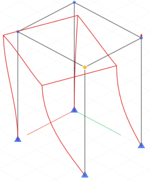
Example of a 3D Frame structure.
Preliminary estimates only. Verify independently for critical applications. See Terms.


