Rubber Tubeform
This module will estimate the state of cure, molding shrinkage and axial stiffness for rubber tubeforms. Various shapes can be modeled. A deformed plots with the rz shear stain plots are also given. A FEM solution is used.
Details (inputs, outputs, assumptions) Read once
Model summary
Inputs: Tubeform general configuration and geometry details including OD and ID. Edge contours. Material properties and molding temperature.
Inputs: Material properties of shear modulus, tan δ and thermal coefficient of thermal expansion. Curing parameters. Molding and room temperatures.
Boundary Conditions: Fixed or free surfaces.
Outputs: Molded shape, state of cure, axial stiffness and shear strains. Static and dynamic stiffness is given.
Hint: A configuration and results can be saved to a JSON file for future use.
Use case: quick what-ifs, sensitivity, and early sizing.
Examples
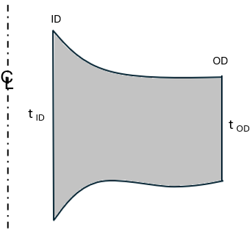
Example of a contoured rubber tubeform.
Preliminary estimates only. Verify independently for critical applications. See Terms.


